Software Programs and Design
All code can be found in the Github for this project.
MCU Code
All MCU Code was done on SEGGER Embedded Studio (IDE) which has a C development environment with a built-in editor and debugger for J-link integration to program the MCU itself.
1. Capacitive Touch Sensor Code
The code uses GPIO signals to determine when the capvalue is high by digitally reading the input pin that the capacitive touch sensor is connected to. When that value goes high, we digitally write to an output GPIO pin (PA5) that is connected electrically to an input FPGA pin (P47). Thus, the incoming capacitive signal when a user touches the nose tells the servo motor and LEDs to trigger and additionally plays the theme song on the DFP player.
In order to not check the capacitive signal when the jaw is open and the robot is only waiting for the IR detector to go off, we implemented a Finite State Machine (FSM) such that we wait for the capacitive signal to go high in the state STATE_WAIT_FOR_CAP, and then when the nose is touched and the capacitive signal toggles we move to state STATE_IR_MODE" where we no longer look for signals from the capacitive touch sensor until Toothless is reset for a new user.
2. IR Proximity Sensor Code
The IR Proximity Sensor produces a voltage when a hand comes near the IR LED which sends a signal to a GPIO pin (PA0) that is specifically programmed with the alternate function that interfaces with the Analog-to-Digital Converter on the MCU.
Once the Capacitive Touch Sensor is triggered the program moves to the next FSM state called STATE_IR_MODE where we are checking if the irvalue input (from the handdetection() function) is high, in which case a signal is sent to an FPGA pin (Pin 2) to trigger the servo motor and LEDs and the ROAR sound is played on the DFP player.
2.1 ADC Initialization and Functions
We separated the code for ADC specific functions and initialization into its own header and .C file for organization. The ADC was intialized in file STM32L432KC_ADC.c where the ADC clock is enabled and set as the system clock (8MHz) divided by 4 (2MHz) to run at a safe but quick speed for reading the analog signals. Because we used the CKMODE register to set the division, we did not need to use the prescaler for the ADC to divide the clock further. We then turned off Deep Power-Down Mode, enabled the voltage regulator, and then delayed for 20μs as per the datasheet. After delaying, the ADC could then be calibrated and configured. We used a single, right-aligned, 12-bit configuration then configured using 1 conversion at a time.
The function readADC() then starts the conversion, waits for the conversion to be finished, then reads off the value through the ADC where it’s called later on in the handdetection() function.
2.2 Hand Detection program
The handdetection() function calls on the readADC() function to read in the converted analog signal from the IR Proximity sensor as a digital value. This digital value is compared against a value we set called HIGH_THRESHOLD which we define in main.h. If the value we receive is above that threshold we determine a hand is being detected and return a digital high, otherwise it stays low. The HIGH_THRESHOLD value was determined through trial and error using the debugger tool and using a printf statement to visually see the incoming digital values when the the open jaw was over the sensor versus when a hand was close to the sensor. The value was chosen such that the sensor was not activated from the bottom of Toothless’ head when the jaw was open slightly or open all the way otherwise the IR would constantly be detecting in an endless loop. A delay of 2 seconds was added between sending the irvalue from pin PB3 to the FPGA on pin P2 and then writing PB3 back to 0 so that the MCU wasn’t checking incoming values from the IR sensor when the jaw was closing on the hand. This gave a good enough pause for the roar to play and the mouth to close and open before another object could be detected.
3. DFPlayer Mini Code
The DFPlayer was encoded entirely on the MCU interfacting with the Capacitive Touch Sensor and IR Proximity Sensor to know when to play the Theme song and ROAR, respectively.
The DFPlayer used UART (Universal Asynchronous Receiver/Transmitter) for serial communication in order to play mp3 files from the TF card connected on it’s hardware. The code used a standard baud rate of 9600 as specified on the datasheet for the USART1 register and a rate of 115200 for debugging on the USART2 register.
Two USART addresses are established in tow pointer variables dfp_usart and dbg_usart. Based on the datasheet the DFPlayer recieves a 10-byte frame which is split up in the function DFP_SendCommand() where we’re able to change the bits for the command, feedback, parameter high byte, parameter low byte, checksum high, and checksum low.
Since we didn’t want any feedback we set that byte to 00 for no reply. The parameters where split to keep the full 16 bits between the high and low bytes.
Other functions such as DFP_Play(), DFP_Pause(), and more would call on DFP_SendCommand() to complete different functions. On the datasheet it identified different addresses associated with different commands such as 0x06 to specify volume, OxOE to pause the song, OxOF to play a specific file on the TF and many more.
For more details on specific commands, this is the datasheet we referenced:
DFPlayer Mini Datasheet with UART Instructions
Then in the while loop, if the Capacitive Touch Sensor is high then after the FPGA signal is sent, the DFP_PlayFolderTrack() function is called to play the theme song Test Drive that’s labeled 001.mp3 in the 01 folder in the TF card.
Similarly when the IR Proximity Sensor is high then after the FPGA signal is sent then the Roar sound on the 002.mp3 file is played.
FPGA Code
All FPGA Code (and testbenches) was done on Lattice Raidant which uses Hremardware Description Languages, in this case System Verilog. The software is able to synthesize and then use the Radiant Programmer tool to program the FPGA itself.
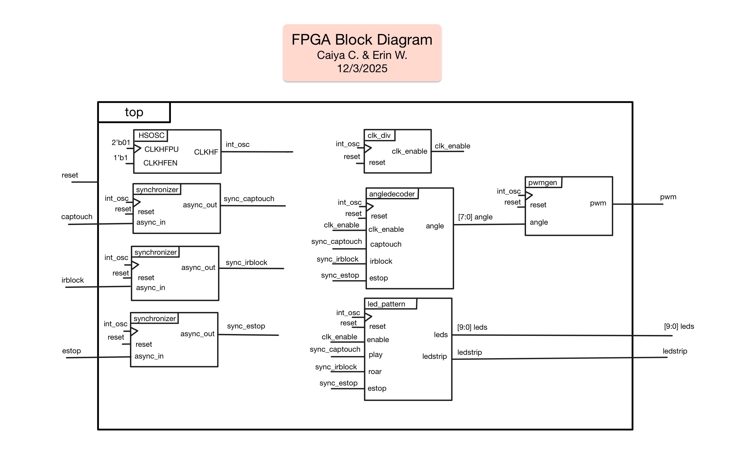
Overall Block Diagram
The complete block diagram can be found below (Figure 1):
1. Servo Motor Code
The Servo Motor was coded mainly through modules angle_decoder and pwm_gen to decide based on the input which angle to open the jaw to. Both modules work in conjunction to open the jaw to the right angle and hold the angle when needed. First, the inputs from the estop and from the MCU, including the capacitive sensor (captouch) and the IR detector (irblock), are sent through the synchronizer to synchronize the inputs. The synchronized inputs are then sent to the angledecoder module which implements an FSM to move from a CLOSED to an OPEN state and then to a SLIGHT state (and back and forth between the three) based on whether the capacitive sensor has been activated or the IR sensor has been activated. servo motor takes in those signals The FSM configuration allowed the angle to be set such that the head would stay fully open until the IR proximity sensor detected a hand and then for the jaw to close just enough to make it feel like the users’ hand is being bitten before returning to the OPEN state. The state only goes back to CLOSED if the estop is triggered for resetting the device for the next user.
For output logic, each state was set to different angles. In the CLOSED state the angle is set to 8’d30 for 30 degrees. In the OPENED state it was set to 8’d150 for 150 degrees. In the SLIGHT state the angle is set to 8’d90 for 90 degrees. These weren’t the exact angles we ended up using but were instead used to differentiate between a fully closed, fully open, and slightly open angle when sending this state to the pwmgen module.
The angle_decoder then sends 8'd30, 8'd150, or 8d90 to the pwmgen module corresponding to whether the mouth should be closed, open, or slightly open respectively. The servo works interestingly in that instead of a PWM signal at a certain frequency to set the angle, the servo bases the angle on the “on-time pulse width” or how long the PWM is on for. For many hobby servos, the servo motor shaft can be rotated from 0° to 180° by varying the pulse width from 1ms to 2 ms. We used a Wokwi blog to help understand how to control the servo motor. Using this information, in the pwmgen module the output pwm signal is set to toggle on for a period of time based on a counter, toggling LOW once a certain counter value is hit such that the pulse width is only on for that specified amount of clock cycles. The counter value that the pwm output toggles on depends on the angle output from the angledecoder module. In order to have the change between opening, chomping, and closing to be visible, the angledecoder module used the clk_enable signal from the clk_div module to slow down the speed from state to state.
To test what the counter values needed to be to reach our desired angles on the mechanical body, we used a seperate test file that sent a hard-coded pwm value to the servo and manually found which counter value matched our desired angles on Toothless’ head.
2. LED Array Code
The LED Array used SRAM (Static Rnadom-Access Memory) loaded on the FPGA’s bitstream to play various LED shows. Since SRAM is volatile, the memory resets everytime the FPGA is reset which introduced the problem of the FPGA erasing the LED show upon every boot. However, loading the pattern into the bitstream allowed us to reload in the LED show automatically everytime the FPGA resets instead of having to load in the show manually. The led_pattern module also used an FSM with states OFF, PLAYING, ROARING, and ON. The LED pattern was stored as an 11 bit string for the 5 white LEDs, 5 green LEDs, and 1 purple LED strip.
When it receives a signal from captouch it goes to state PLAYING and plays the pattern of the green LEDs, slowly turning on in sequence, followed by the white ones, and then ending by moving to the ON state with all white LEDs and the purple LED strip on. In the ROARING state the LED pattern flashes the green LEDs on and off three times before returning to the ON state. In order to have the change between each step of the LED sequence to be visible, the led_pattern used the clk_enable signal from the clk_div module to slow down the speed from state to state and step to step such that the eye could see every change clearly.
3. Synchronizer code
The synchronizer module uses two flip flops to synchronize an asynchronous input and output a synchronous signal to the rest of the modules. The module was used to synchronize the captouch and irblock inputs from the MCU and the estop input from the external button.
4. Clock divider code
The clk_div module uses a counter to slow the internal HSOSC clock down such that the changes between states for the jaw and the LEDs were visible. The module does this by sending a high pulse every 2000000 cycles such that with an internal clock of 24MHz, the states of angledecoder and led_pattern change on a 12Hz frequency.