Software Test Benches
top Testbench (HSOSC)
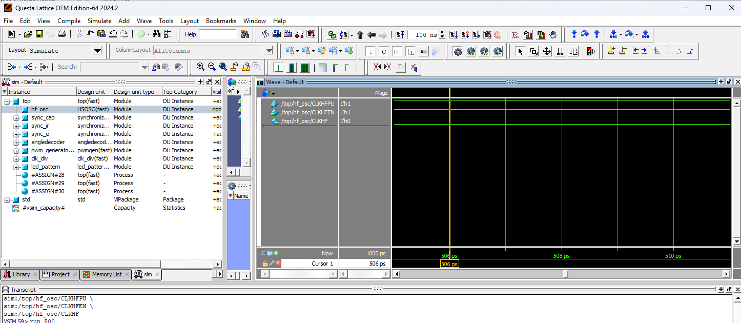
top module showing that HSOSC toggles.
From the testbench results of the top module (Figure 1), we can see that HSOSC successfully triggered, which means the int_osc clock is successfully sent to the rest of the modules which all share int_osc as a clock.
synchronizer Testbench

synchronizer module showing that the sync_out output gets the async_in after two clock cycles.
From the testbench results of the synchronizer module (Figure 2), we can see that the sync_out output matches the async_in input after two clock cycles. The input and output signals are all 1-bit due to the inputs into the top module all being 1-bit signals of HIGH or LOW.
clk_div Testbench

clk_div module showing that the clk_enable output toggles when the counter reaches 2000000 or 2000000 cycles.
From the testbench results of the clk_div module (Figure 3), we can see that the clk_enable output successfully toggles at 2000000 clock cycles. This slows down the clock for the other modules such that the change in head positions and the led pattern are visible to the eye.
angle_decoder Testbench
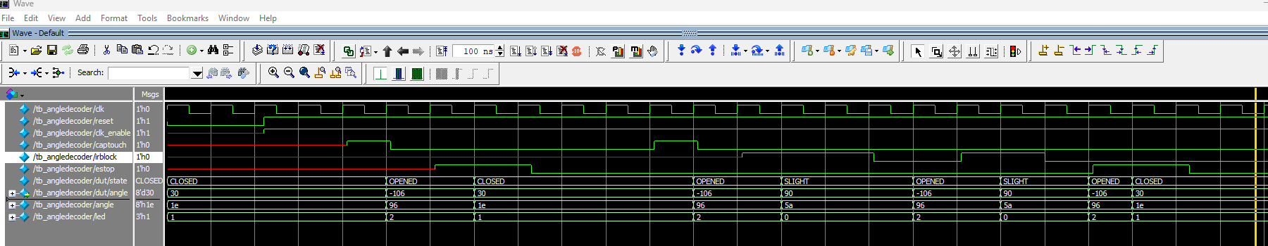
angle_decoder module showing that the each state is visited correctly. The state changes from CLOSED to OPENED after captouch goes high, from OPENED to SLIGHT when irblock goes high, stays at SLIGHT when irblock stays high, back to OPENED from SLIGHT when irblock goes low, and akways back to CLOSED when estop goes high.
From the testbench results of the angle_decoder module (Figure 4), we can see that the program successfully moves to the right state when prompted by the expected input. CLOSED goes to OPENED when captouch goes high an the nose is touched. Then, the program moves from OPENED to SLIGHT when irblock goes high, and stays at SLIGHT when irblockis still high. And then only moves back to OPENED from SLIGHT when irblock goes low. The state goes to CLOSED when estop is is prompted.
pwmgen Testbench
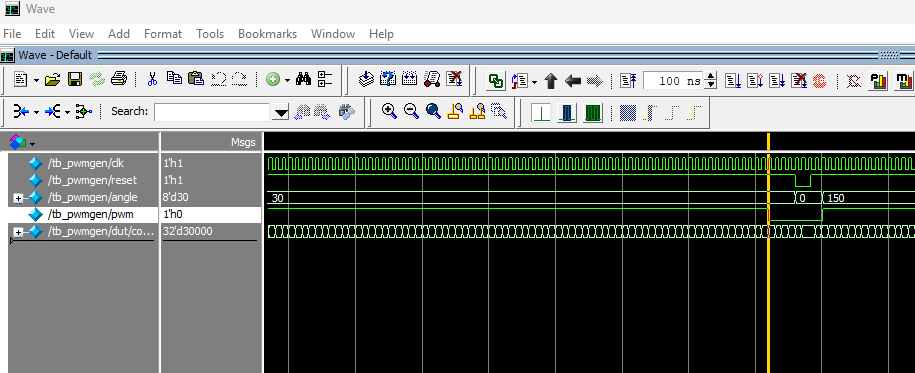
pwmgen module shows that the pwm output successfully toggles LOW when counter is 30000 and angle is 8'd30.
From the testbench results of the pwmgen module above, we can see that the pwm output successfuly toggles from high to low when counter is 30000 when the input angle is 8'd30 (Figure 5). This means the servo is successfully sent the PWM signal for the CLOSED state.
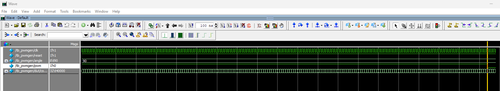
pwmgen module shows that the pwm output successfully toggles LOW when counter is 40000 and angle is 8'd90.
From the testbench results of the pwmgen module above, we can see that the pwm output successfuly toggles from high to low when counter is 40000 when the input angle is 8'd90 (Figure 6). This means the servo is successfully sent the PWM signal for the SLIGHT state.
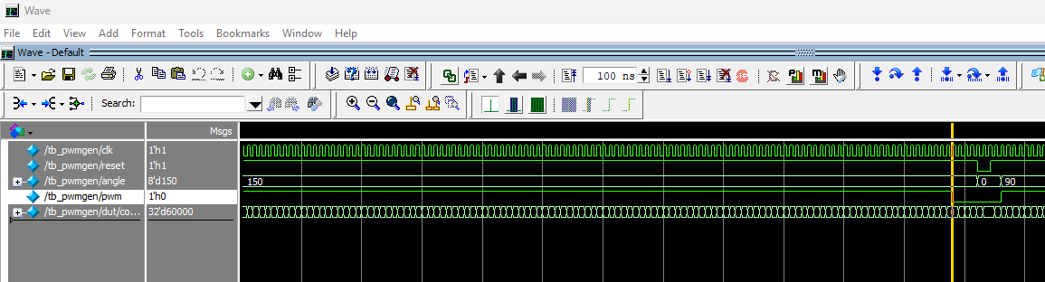
pwmgen module shows that the pwm output successfully toggles LOW when counter is 60000 and angle is 8'd150.
From the testbench results of the pwmgen module above, we can see that the pwm output successfuly toggles from high to low when counter is 60000 when the input angle is 8'd150 (Figure 7). This means the servo is successfully sent the PWM signal for the OPEN state.
led_pattern Testbench
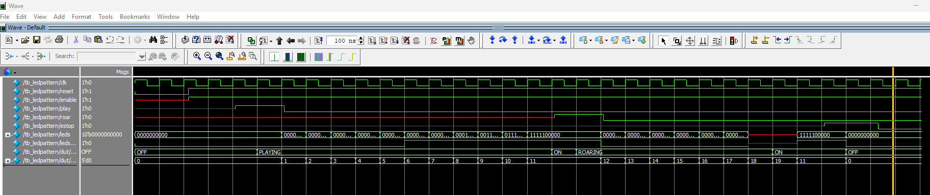
led_pattern module shows that the leds and ledstrip output match expected outputs with the expected input triggers. The pattern_index also successfully increases in the expected order.
From the testbench results of the led_pattern module (Figure 8), we can see that the pattern_index reaches the right numbers in the right order and begins increasing in response to the appropriate input. Whe play goes high, the pattern_index increases from 0 to 11 and stays at 11 until roar goes high. Then, the index increases up to 17 before stopping the pattern and returning to pattern 11. This matches the software and expected outputs, meaning the LED show will match the expected pattern based on the expected inputs.