Lab 1 Report
Lab Hours
I spent 24 hours working on this lab.
Introduction
Lab 1 dealt with setting up and testing the FPGA including soldering all parts of the board and writing SystemVerilog code to verify the LEDs and interface with a 7-segment display on a breadboard.
Design and Testing Methodology
Blinking LED2
The on-board high-speed oscillator (HSOSC) from the iCE40 UltraPlus primitive library was used to generate a clock signal at 24 MHz. Then, a counter was used to divide the high frequency clock signal to drive an external LED (LED2) such that it blinks at 2.4 Hz.
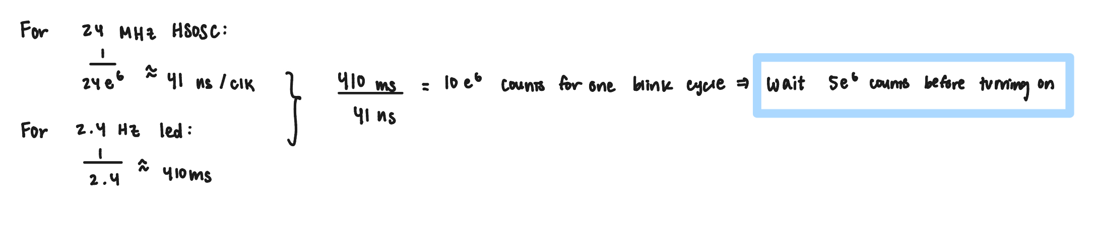
The calculation in Figure 1 derived that the counter needed to reach 5000000 before setting the LED HIGH in order to blink the LED at 2.4 Hz with a 50% duty cycle.
Resistor choice for 7-segment Display
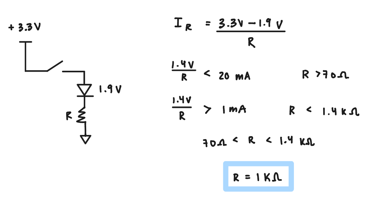
The calculation in Figure 2 derived 1kΩ as an appropriate resistor to provide ~1.9 mA to the LED segments.
Technical Documentation
The source code for the project can be found in the associated Github repository
Block Diagram
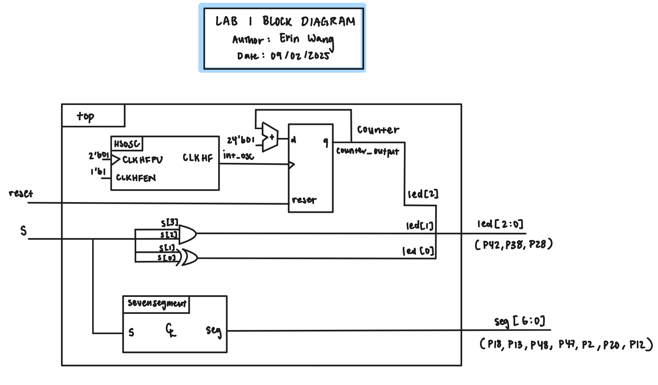
The block diagram in Figure 3 demonstrates the overall architecture of the design. The top-level module top includes two submodules: the high-speed oscillator block (HSOSC) and the 7-segment display module (sevensegment). The programming for the leds were placed in the top module.
Schematic
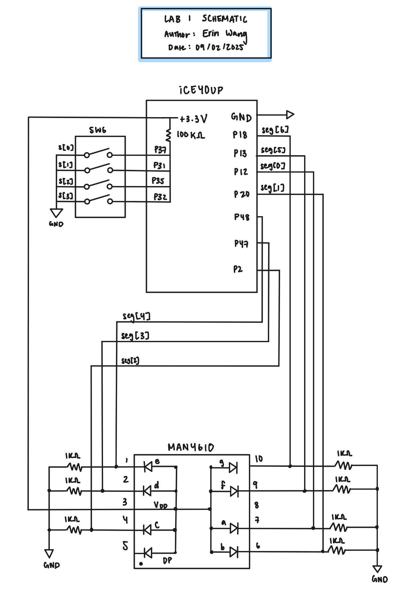
Figure 4 shows the physical layout of the design. An internal 100 kΩ pullup resistor was used to ensure the active low reset pin for the switches was not floating. The output 7-segment diodes were connected using a 1kΩ current-limiting resistor to ensure the output current (~1.2 mA) did not exceed the maximum output current of the FPGA I/O pins. The figure also shows which pin number corresponds to which segment (i.e. a,b,c…) of the 7-segment display.

Figure 5 depicts the assignment of letters to the output display. In the program, seg[0] corresponds to a, seg[1] to b, and so on.
Results and Discussion
Testbench Simulation

The design met all intended design objectives. Figure 6 shows a screenshot of the QuestaSim simulation for the top module’s testbench tb_top. The simulated outputs of led and seg match their respective expected outputs.

Figure 7 shows a screenshot of the QuestaSim simulation for the sevensegment module’s testbench tb_sevseg. The simulated outputs of seg match the expected outputs.
If the design wanted to reuse the clock divider program, a separate module could be developed for the clock divider that takes the HSOSC int_osc output as an input.
Conclusion
The design successfully blinked LED2 using the on-board high-speed oscillator, programmed LED1 and LED0 to the given truth table corresponding to s[3:2] and s[1:0] respectively, and displayed on the 7-segment display a single hexadecimal digit corresponding to the switches s[3:0] such that each digit is unique/distinguishable from the rest.
AI Prototype and Reflection
The first run with Claude AI produced a code very similar to the one I had written for the led_blinker by toggling the led under an always_ff statement with the counter. Some key differences was that the program used the SB_HFOSC module rather than the HSOSC which was new to me and was also unrecognized by Radiant giving a “instantiating unknown module” error.
After feeding the error back into the LLM, the LLM fed back to declare the primitive with blackbox attribute which is also completely new to me. However parsing this still provided an error that CLKHF_DIV is not defined in this module. The instantiation of the SB_HFOSC module seemed to run into an error where the parameter in the module was not defined when later used in the module.
Another key difference and something new to me was that the program used localparam int to initialize a maximum counter and the width of the counter. The width of the counter used the code $clog2(COUNTER_MAX + 1) which I have never seen.
If I were to use the LLM again, I would like to tell the LLM what modules to use. The issue seemed to be with SB_HFOSC so feeding the LLM explicitly to use HSOSC could be quicker to getting towards a working code. Doing this actually changed the error to duplicate module name because the LLM program was trying to delcare the HSOSC primitive. Then feeding this error the LLM replied that the error is likely due to the HSOSC module already being available and it deleted the primitive declaration. After this deletion the code synthesized with no errors!
I think the quality of the output is quite high. Each new section of code is commented with an overarching comment of the module’s function at the top. The only thing is that the LLM can get really stuck on executing the code one way and sometimes better quality code can be written by knowing multiple avenues of which to implement the code. So feeding the desired packages or modules can be really helpful in producing successful LLM code.