Lab 4 Report
Lab Hours
I spent 30 hours on this lab.
Introduction
Lab 4 involved learning how to setup header files for the MCU by practicing making a header file for the timers TIM15 and TIM16 as well as in writing to registers to output frequencies corresponding to different notes.
Design and Testing Methodology
Verifying 1% Accuracy for 220 Hz to 1000 Hz Frequencies
In order to create a PWM of different frequencies, I made use of timer TIM16 on the MCU to slow down an incoming clock and turn on and off given a number of ticks corresponding to the period of the input frequency. The divider for the incoming clock had to be selected in order to accomodate 220 Hz to 1000 Hz without overflowing the prescaler or the timer counter. I was able to control the AHB2, APB2, and TIM16 prescaler. However, I chose only to manipulate the 16-bit TIM16 prescaler as it had greater flexibility with being able to be set to values 1 to 65536 and meant that the other peripherals using AHB2 and APB2 wouldn’t be affected by a slower clock. Because I used the PLL as the SYSCLK, the incoming signal to TIM16 was 80 MHz. I chose the AHB2 prescaler to be /1, the APB2 prescaler to be /1, and the TIM16 prescaler to be 7. With the TIM16 prescaler (PSC). the input clock to TIM16 is divided by PSC + 1such that
\[ TIM16_{frequency} = {\frac{80 MHz}{7+1}} = 10 MHz \]
Because the TIM16 counter upcounts everytime it sees a clock edge that means that at an incoming 10 MHz clock provides 10000000 ticks per second. However, due to the limitations of the MCU, the division rounds down. This results in the following discrepancy between input and output note frequency:
For 220 Hz…
\[ actual\:counter = {\frac{10000000 {\frac{ticks}{s}}}{220 {\frac{1}{s}}}} = 45454.54545 \: ticks \] \[ calculated\:counter = {\frac{10000000 {\frac{ticks}{s}}}{220 {\frac{1}{s}}}} = 45454 : ticks \] \[ calculated\:frequency = {\frac{10000000 {\frac{ticks}{s}}}{45454 \:ticks}} = 220.0026400317 Hz \]
\[ \begin{align*} percent \: difference &= {\frac{calculated \: frequency - actual \: frequency}{actual \: frequency}} * 100\% \\ &= {\frac{220.0026400317 Hz - 220 Hz}{220 Hz}} * 100\% \\ &= 0.0012\% \end{align*} \]
For 1000 Hz…
\[ actual\:counter = {\frac{10000000 {\frac{ticks}{s}}}{1000 {\frac{1}{s}}}} = 10000 \: ticks \] \[ calculated\:counter = {\frac{10000000 {\frac{ticks}{s}}}{1000 {\frac{1}{s}}}} = 10000 \: ticks \] \[ calculated\:frequency = {\frac{10000000 {\frac{ticks}{s}}}{10000 \:ticks}} = 1000 Hz \]
\[ \begin{align*} percent \: difference &= {\frac{calculated \: frequency - actual \: frequency}{actual \: frequency}} * 100\% \\ &= {\frac{1000 Hz - 1000 Hz}{10000 Hz}} * 100\% \\ &= 0\% \end{align*} \]
For random 337 Hz…
\[ actual\:counter = {\frac{10000000 {\frac{ticks}{s}}}{337 {\frac{1}{s}}}} = 29673.590504451 \: ticks \] \[ calculated\:counter = {\frac{10000000 {\frac{ticks}{s}}}{337 {\frac{1}{s}}}} = 29673 \: ticks \] \[ calculated\:frequency = {\frac{10000000 {\frac{ticks}{s}}}{29673 \:ticks}} = 337.0067064335 Hz \]
\[ \begin{align*} percent \: difference &= {\frac{calculated \: frequency - actual \: frequency}{actual \: frequency}} * 100\% \\ &= {\frac{337.0067064335 Hz - 337 Hz}{337 Hz}} * 100\% \\ &= 0.00199\% \end{align*} \]
Expected Range Conclusion
Therefore, the PSC of 7 allows for individual pitches to be calculated within %1 accuracy when between 220 Hz and 1000 Hz.
Max/Min Duration
For the note duration, I used TIM15 for my delay and set the PSC to 7999 such that the incoming clock would be as such.
\[ TIM15_{frequency} = {\frac{80 MHz}{7999+1}} = 10 kHz \]
According to the STM reference manual, the TIM15 counter is able to go from 1 to 65536. Using these values, the calculated max and min durations are as follows.
Max Duration
\[ max \: duration = {\frac{655356 \: ticks}{10000 {\frac{ticks}{s}}}} = 6.5536 \: s = 6553.6 \: ms \]
Min Duration
\[ min \: duration = {\frac{1 \: tick}{10000 {\frac{ticks}{s}}}} = 0.0001 \: s = 0.1 \: ms \]
Duration Conclusion
By calculation the theoretical max/min duration are 6553.6 ms and 0.1 ms respectively. However, because the counter can only handle integer inputs, this is rounded to 6553 and 0 ms respectively.
Max/Min Frequency
According to the STM reference manual, the TIM16 counter is able to go from 1 to 65536. Using these values and the TIM16 frequency as calculated above to be 10 MHz, the calculated max and min frequencies are as follows.
Max Frequency
\[ max \: frequency = {\frac{10000000 {\frac{ticks}{s}}}{1 \: tick}} = 10 \: MHz \]
Min Frequency
\[ max \: frequency = {\frac{10000000 {\frac{ticks}{s}}}{655356 \: ticks}} = 152.588 \: Hz \]
Duration Conclusion
By calculation the theoretical max/min frequency are 10 MHz and 152.588 Hz respectively. However, because the counter can only handle integer inputs, this is rounded to 10 MHz and 153 Hz respectively.
LM386 Circuit Design
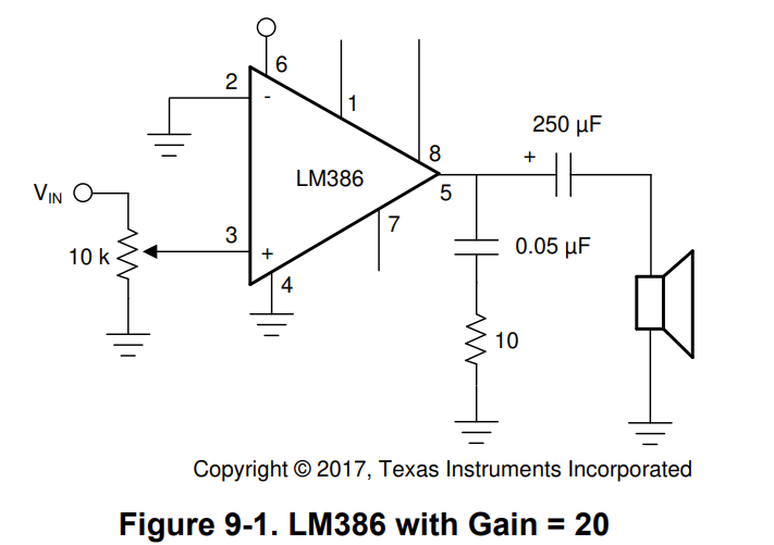
In order to properly amplify the output PWM signal to the speaker, I passed the signal through a potentiometer and then into an LM386. The LM386 circuit I used was from the LM386 Datasheet for a gain of 20 (see Figure 1). The only thing I added to this circuit was a 0.1 μF bypass capacitor to deal with any noise in my power signal.
Technical Documentation
The source code for the project can be found in the associated Github repository
Schematic
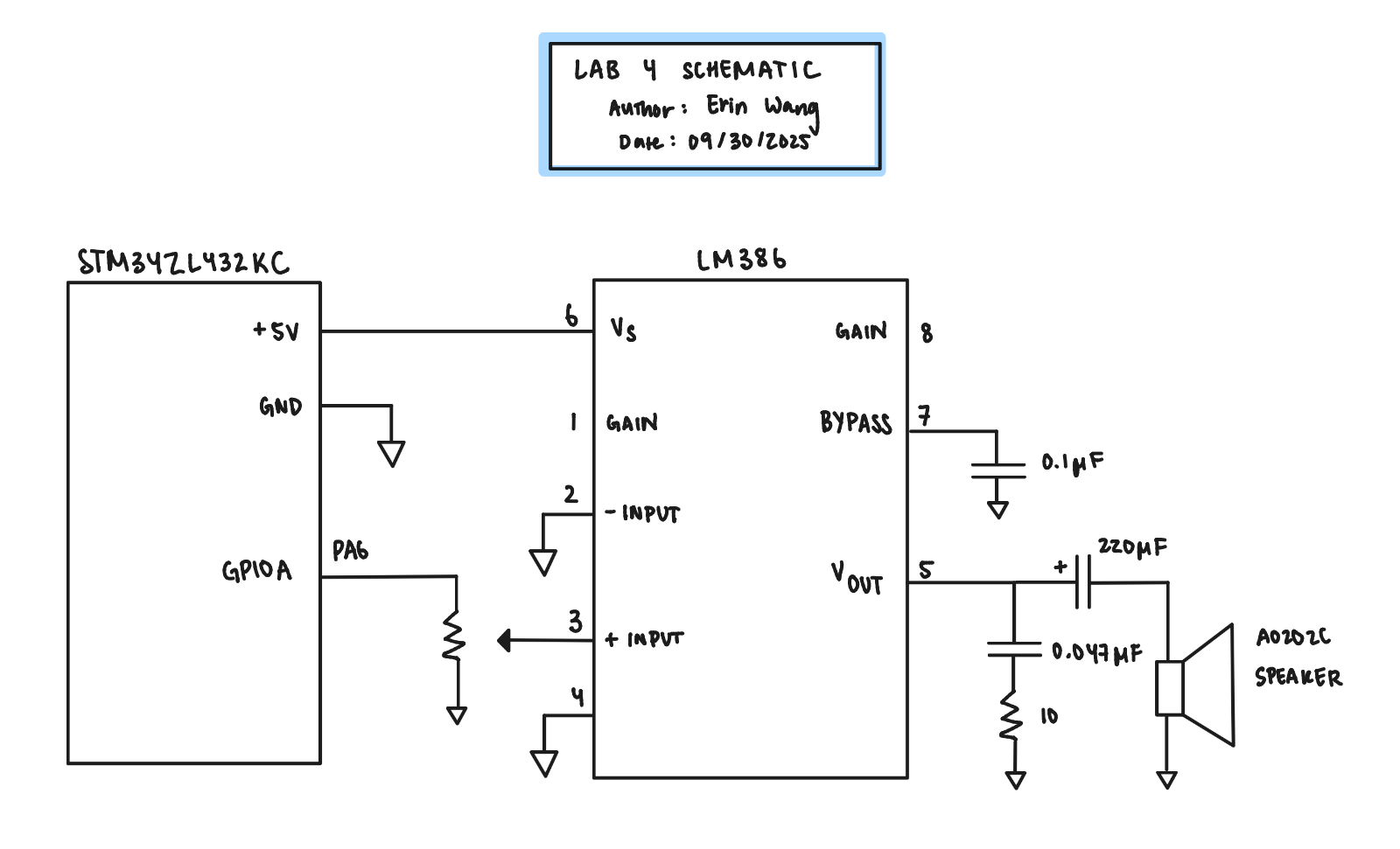
Figure 2 shows the physical layout of the design. The choice of values for each component is described in the design and testing methodology. The PWM signal comes from PA6 out of the GPIOA port bank.
Results and Discussion
Picture of Circuit and Video of Chosen Composition (“Soda Pop” by the Saja Boys)
The working circuit is pictured below in Figure 3.
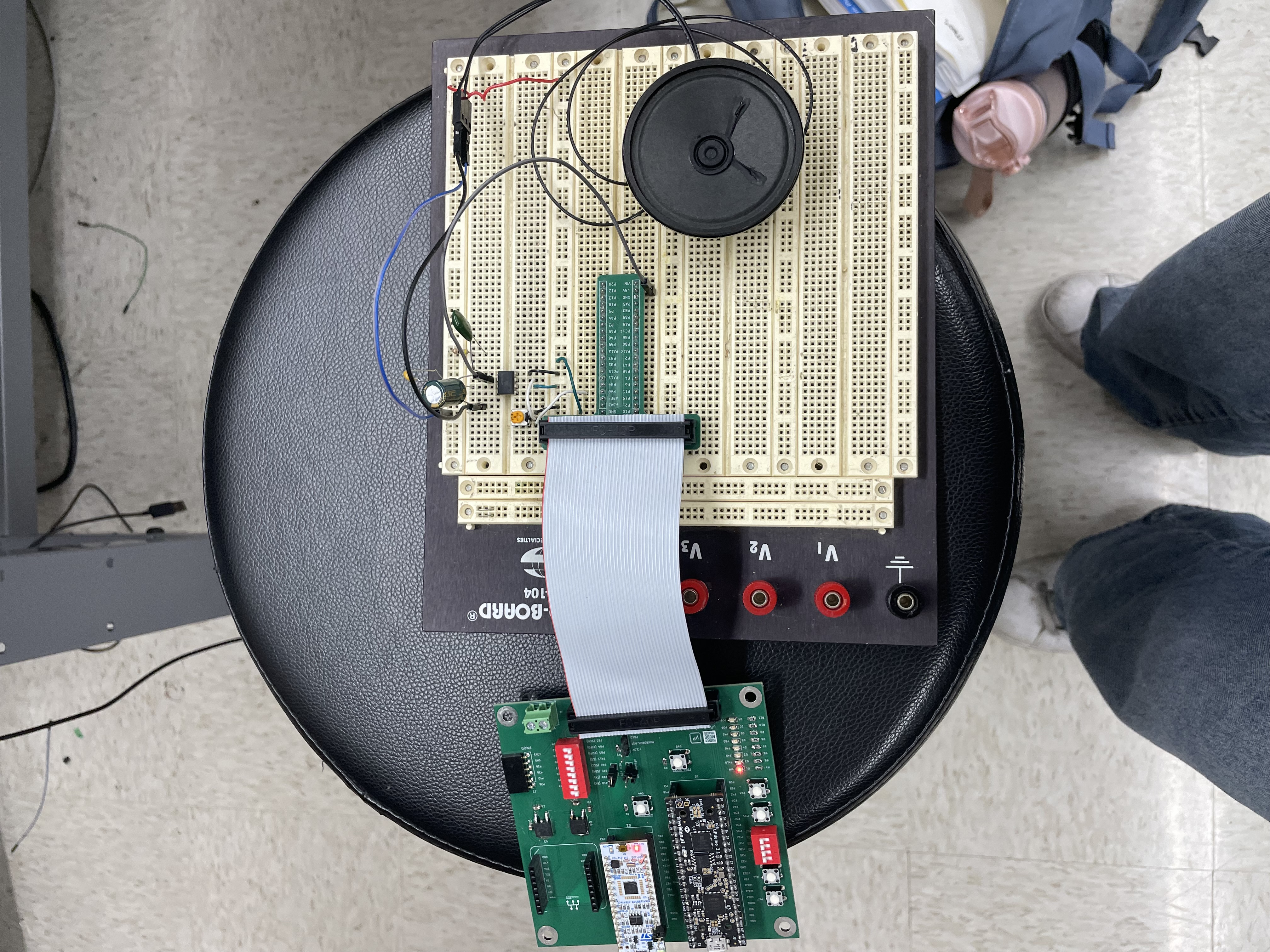
I chose “Soda Pop” by the Saja Boys from the movie Kpop Demon Hunters as my extra song. Here is the circuit playing the tune.
Conclusion
The design successfully plays Für Elise at the right tempo and with proper rests. Individual pitches are calculated to be accurate within 1% across the frequency range of 220-1000 Hz. The code uses #define macros for memory-mapped registers.The design incorporates a potentiometer and is able to play another song of my choice.
Overall a success!
AI Prototype and Reflection
Best Timer Choice: TIM2
The Claude AI said that the best timer choice would be TIM2 because it has a 32-bit timer which allows PWM output mode, gives more flexibility for the prescaler, and has multiple channels that can be routed to the GPIO pins via alternate functions. However, the AI said alternatively TIM1 or TIM15/16 also work well just with a smaller counter.
This makes sense to me as the flexibility would be an important part to having a greater range of durations to be able to play as well as less concern with overflowing the counter.
Relevant Formulae
According to Claudem the output frequency is determined by:
f_out = f_timer / ((PSC + 1) × (ARR + 1))
Claude defines f_{out} as the timer clock frequency of typically 80 MHz.
For a 50% duty cycle PWM, Claude writes the equation as
CCRx = ARR / 2
Both of the equations above are the equations I used to calculate my counter frequency and a 50% duty cycle.
Example Calculations
The following is quoted from the Claude AI:
Claude AI Example Calculations
For 220 Hz with 80 MHz timer clock:
Target count = 80,000,000 / 220 = 363,636 Choose PSC = 99 (divides by 100) ARR = 80,000,000 / (100 × 220) - 1 = 3,636 - 1 = 3,635 Actual frequency = 80,000,000 / (100 × 3,636) = 220.02 Hz
For 1 kHz:
PSC = 79 (divides by 80) ARR = 80,000,000 / (80 × 1000) - 1 = 999 Actual frequency = 1,000 Hz exactly
I actually really like how the AI calcualted the right ARR. I simply knew from debugging my program that the division rounds down and so I used that when calculating the target. However, it seems like the AI is changing PSC between the two frequencies whereas my program only uses one PSC to capture the full range from 220 Hz to 1kHz.
Key Register to Configure
1. RCC Registers - Enable Clocks
RCC->APB1ENR1 |= RCC_APB1ENR1_TIM2EN;  // Enable TIM2 clock

RCC->AHB2ENR |= RCC_AHB2ENR_GPIOAEN;   // Enable GPIO port clock
Because I used TIM15/16 I enabled APB2ENR1 and AHB2ENR.
2. GPIO Configuration - Set alternate function
For TIM2_CH1 on PA0 (example):
GPIOA->MODER &= ~GPIO_MODER_MODE0;     // Clear mode bits

GPIOA->MODER |= GPIO_MODER_MODE0_1;    // Set to alternate function

GPIOA->AFR[0] |= (1 << GPIO_AFRL_AFSEL0_Pos);  // AF1 for TIM2
I used the pinMode function given to us in the tutorial GPIO header, however I did need to set AFR for PIN16 for my output PWM signal.
3. TIM2 Registers
TIM2->PSC = 99; // For 220 Hz example

TIM2->CCR1 = 1818;  // 50% duty cycle (ARR/2)

TIM2->CCMR1 |= (6 << TIM_CCMR1_OC1M_Pos);  // PWM mode 1

TIM2->CCMR1 |= TIM_CCMR1_OC1PE;            // Preload enable

TIM2->CCER |= TIM_CCER_CC1E;  // Enable output on channel 1

TIM2->CR1 |= TIM_CR1_ARPE;  // Auto-reload preload enable

TIM2->CR1 |= TIM_CR1_CEN;   // Counter enable (start timer)

TIM2->EGR |= TIM_EGR_UG;  // Generate update event to load registers
I did use all of these but I also ended up needing to set BDTR as well for PWM output mode.
GPIO Pin Mapping Options (TIM2)
PA0 - TIM2_CH1 (AF1)
PA1 - TIM2_CH2 (AF1)
PA5 - TIM2_CH1 (AF1)
PB3 - TIM2_CH2 (AF1)
Check your specific board’s pinout to ensure the pin is accessible on the nucleo headers.
I used PA6 because that was the Channel 1 for TIM16.
Summary Configuration Sequence
- Enable RCC clocks (timer + GPIO)
- Configure GPIO pin for alternate function
- Set PSC and ARR for desired frequency
- Set CCRx for duty cycle
- Configure PWM mode in CCMR register
- Enable output in CCER register
- Enable counter in CR1
These were the steps I used with the enable RCC clocks and configure GPIO pin in my main function whereas the rest of the steps were held in their own function in my TIMX.c file.