Lab 5 Report
Lab Hours
I spent 20 hours on this lab.
Introduction
Lab 5 involved learning how to use interrupts to quickly and accurately sample inputs by calculating the velocity of a motor using quadrature encoders.
Design and Testing Methodology
Computing Velocity
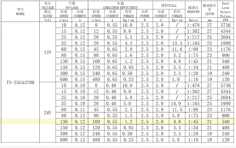
For using a 12V 150RPM motor, the pulses per revolution (PPR) was 408 according to the motor’s datasheet (see Figure 1). In order to get the velocity in revolutions per second (RPS), a counter was used to find pulses per second (PPS). Because the lab uses quadrature encoder with an A signal and a B signal for the motor and the interrupt flag waves at the rising edge and falling edge of both A and B, the counter in my program counts how many flags were seen in a 1 second delay needs to divided by 4 in order to find the actual PPS:
\[ PPS = \frac{counter}{4} \]
To get RPS, the PPS then needs to account for how many pulses are in one revolution:
\[ RPS = \frac{PPS}{PPR} = \frac{PPS}{408} \]
Using the above calculations, I derived the speed in revolutions per second. However, for direction this depends on the which clock is leading. The interrupt EXTI1 assumes input A is leading and thus if input A and B are not the same, that means this assumption is true, thus the clock is moving clockwise and the counter should be increased (CW is positive). If input A and B are the same, then the assumption is not true, thus the clock is moving counter-clockwise and the counter should be decreased (CCW is negative). The interrupt EXTI2 assumes input B is leading and uses the same logic except if the inputs are the same then the clock if moving CCW, and if the inputs are not the same then the clock is moving CW. Having both interrupts is necessary in order to check the rising and falling edges of BOTH A and B inputs.
Checking Velocity at 12V
Since the motor used is rated for 150 RPM at 12V, I can check that the measured and printed velocity is the same as the actual true velocity. If the motor is moving at 150 RPM this can be converted to RPS:
\[ RPS = \frac{RPM}{60} = \frac{150}{60} = 2.5 \: rev/s \]
Thus, the measured velocity should be around 2.5 rev/s when the motor is powered at 12V.
Interrupts versus Manual Polling
While interrupts stop the main loop from continuing until the interrupt task is done, manual polling happens in parallel or while the main loop is running. This means manual polling misses edges while the delay is running. The pulses the polling misses can be calculated using the motor’s PPR. Using an oscilloscope on the quadrature encodings, I found the quadrature encoder signal was running at 1.86 kHz which is 1860 PPS. Using this I was able to find how many RPS we would miss in the manual polling.
\[ RPS_{lost} = \frac{PPS_{quadrature}}{PPR} = \frac{1860}{408} = 4.559 \: rev/s \]
Thus, we would lose approximately 5 revolutions per second using manual polling. Because the interrupts capture every edge of the quadrature encoder and stops the main loop from running while the interrupt is handling the interrupt task, the interrupts provide the highest-resolution measurement of the velocity whereas the manual polling loses resolution.
Technical Documentation
The source code for the project can be found in the associated Github repository
Schematic
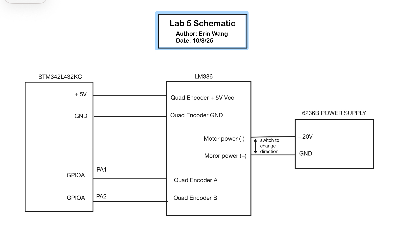
Figure 2 shows the physical layout of the design. The GPIOA pins PA1 and PA2 were chosen for their ability to handle the 5V output from the MCU into the motor.
Flow Chart
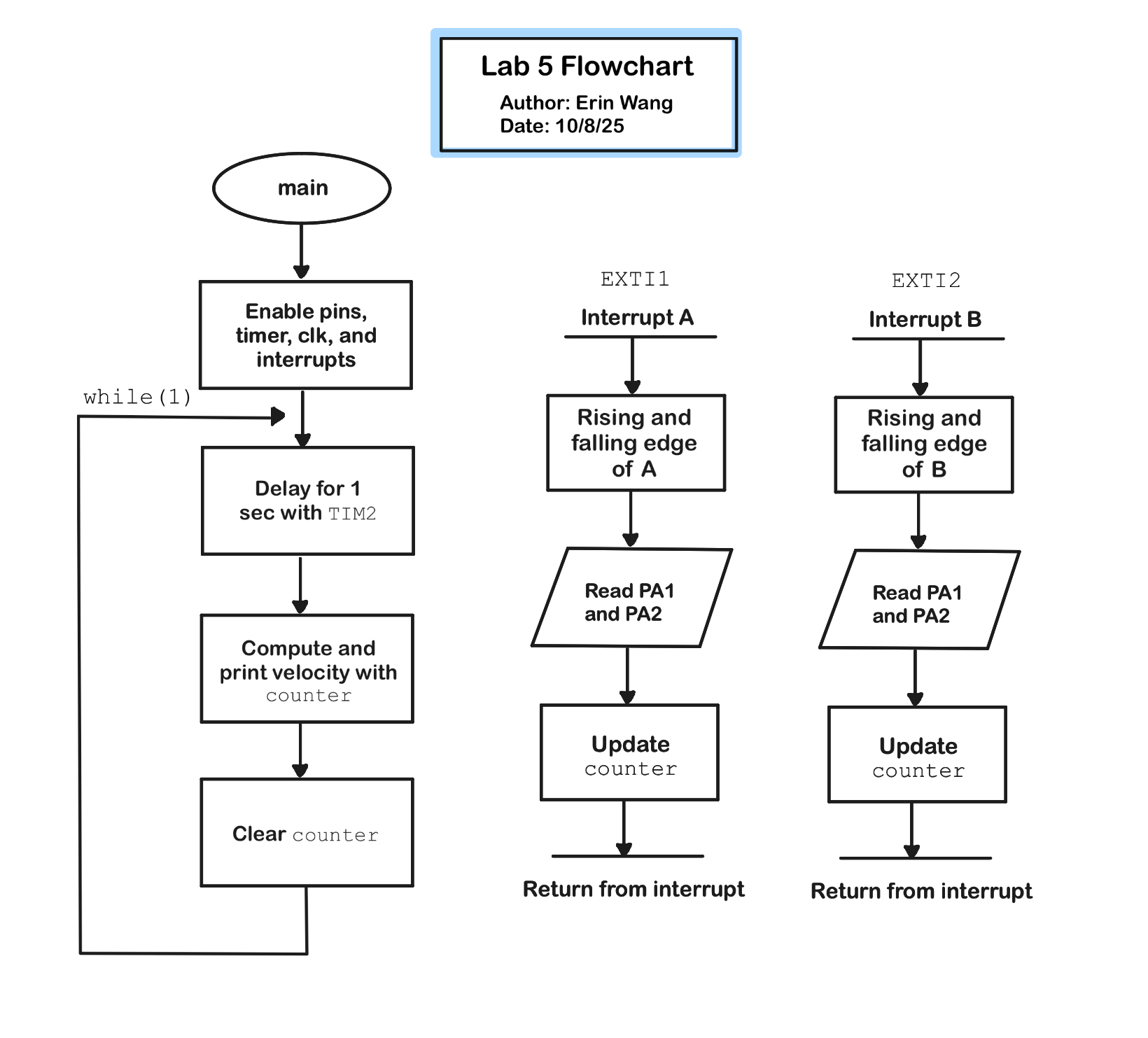
Figure 3 shows the flow of the program including the main function and the interrupt functions for the A and B signals of the quadrature encoder. ## Results and Discussion
Conclusion
The design successfully outputs the velocity with the correct direction with at least a 1 Hz update rate. The program measured the velocity to be 2.8 rev/s at 12V which is very close to our expected velocity of 2.5 rev/s. The program utilizes all edges of the quadrature encoders, does not miss any edges at high speeds, reports 0 when the fan is unmoving, and does not report 0 at low speeds (has high resolution).
Overall a success!
AI Prototype and Reflection
The Claude AI did not pass on the first run. The program included the header "stm32l4xx_hal.h" which was not recognized by Segger. I asked the AI to instead use <stm32l432xx.h>. This change did create a buildable solution. However, there was no code to show the velocity anywhere. So I prompted the AI to output the velocity using printf.
The AI actually gave me two methods: one for Hardware Encoder Mode that uses TIM2 encoder interface and no interrupts and another for Software Encoder Mode that uses the EXTI interrupts like I did. Another fun thing the AI did was also find the position not just the velocity. To keep things simple I asked just for velocity and to use Method 2.
Method 2: Software Encoder Mode
/* Quadrature Encoder Interface for STM32L432KC
 * GPIO Interrupt Mode - Velocity Only
 * Direct register access without HAL
 */

#include <stm32l432xx.h>
#include <stdio.h>

/* ============================================
 * PRINTF RETARGET FOR SWO/ITM (ST-Link)
 * ============================================ */

int _write(int file, char *ptr, int len)
{
    for(int i = 0; i < len; i++) {
        ITM_SendChar((*ptr++));
    }
    return len;
}

/* ============================================
 * GPIO INTERRUPT MODE - VELOCITY CALCULATION
 * Software quadrature decoding using EXTI interrupts
 * Connect encoder to PA0 (Channel A) and PA1 (Channel B)
 * ============================================ */

#define ENCODER_A_PIN 0
#define ENCODER_B_PIN 1

volatile int32_t encoder_count = 0;
volatile int32_t encoder_velocity = 0;  // counts per second
volatile uint8_t last_state = 0;

void Encoder_GPIO_Init(void)
{
    // Enable clocks for GPIOA and SYSCFG
    RCC->AHB2ENR |= RCC_AHB2ENR_GPIOAEN;
    RCC->APB2ENR |= RCC_APB2ENR_SYSCFGEN;

    // Configure PA0 and PA1 as inputs
    GPIOA->MODER &= ~(GPIO_MODER_MODE0 | GPIO_MODER_MODE1);

    // Enable pull-ups
    GPIOA->PUPDR &= ~(GPIO_PUPDR_PUPD0 | GPIO_PUPDR_PUPD1);
    GPIOA->PUPDR |= (GPIO_PUPDR_PUPD0_0 | GPIO_PUPDR_PUPD1_0);

    // Configure EXTI for PA0 and PA1
    SYSCFG->EXTICR[0] &= ~(SYSCFG_EXTICR1_EXTI0 | SYSCFG_EXTICR1_EXTI1);
    // EXTI0 and EXTI1 connected to PA0 and PA1 (value 0 = GPIOA)

    // Enable rising and falling edge triggers
    EXTI->RTSR1 |= (EXTI_RTSR1_RT0 | EXTI_RTSR1_RT1);
    EXTI->FTSR1 |= (EXTI_FTSR1_FT0 | EXTI_FTSR1_FT1);

    // Unmask interrupts
    EXTI->IMR1 |= (EXTI_IMR1_IM0 | EXTI_IMR1_IM1);

    // Enable NVIC interrupts
    NVIC_SetPriority(EXTI0_IRQn, 2);
    NVIC_EnableIRQ(EXTI0_IRQn);

    NVIC_SetPriority(EXTI1_IRQn, 2);
    NVIC_EnableIRQ(EXTI1_IRQn);

    // Read initial state
    last_state = ((GPIOA->IDR & (1 << ENCODER_A_PIN)) ? 2 : 0) |
                 ((GPIOA->IDR & (1 << ENCODER_B_PIN)) ? 1 : 0);
}

void Encoder_Process(void)
{
    uint8_t current_state = ((GPIOA->IDR & (1 << ENCODER_A_PIN)) ? 2 : 0) |
                            ((GPIOA->IDR & (1 << ENCODER_B_PIN)) ? 1 : 0);

    // State transition table for quadrature decoding
    int8_t direction = 0;
    uint8_t transition = (last_state << 2) | current_state;

    switch(transition) {
        // Clockwise transitions
        case 0b0001: case 0b0111: case 0b1110: case 0b1000:
            direction = 1;
            break;
        // Counter-clockwise transitions
        case 0b0010: case 0b1011: case 0b1101: case 0b0100:
            direction = -1;
            break;
        // Invalid or no change
        default:
            direction = 0;
            break;
    }

    encoder_count += direction;
    last_state = current_state;
}

// EXTI0 interrupt handler (Channel A on PA0)
void EXTI0_IRQHandler(void)
{
    if(EXTI->PR1 & EXTI_PR1_PIF0) {
        EXTI->PR1 = EXTI_PR1_PIF0;  // Clear pending bit
        Encoder_Process();
    }
}

// EXTI1 interrupt handler (Channel B on PA1)
void EXTI1_IRQHandler(void)
{
    if(EXTI->PR1 & EXTI_PR1_PIF1) {
        EXTI->PR1 = EXTI_PR1_PIF1;  // Clear pending bit
        Encoder_Process();
    }
}

void Encoder_CalculateVelocity(void)
{
    static int32_t last_count = 0;
    int32_t current_count = encoder_count;

    // Calculate change in count (delta)
    int32_t delta = current_count - last_count;

    // Velocity in counts per second (assuming 100ms sampling = 10 Hz)
    encoder_velocity = delta * 10;

    last_count = current_count;
}

int32_t Encoder_GetVelocity(void)
{
    return encoder_velocity;
}

/* ============================================
 * SYSTICK TIMER FOR VELOCITY SAMPLING
 * ============================================ */

void SysTick_Init(uint32_t ticks)
{
    SysTick->LOAD = ticks - 1;
    SysTick->VAL = 0;
    SysTick->CTRL = SysTick_CTRL_CLKSOURCE_Msk |
                    SysTick_CTRL_TICKINT_Msk |
                    SysTick_CTRL_ENABLE_Msk;
}

void SysTick_Handler(void)
{
    // Calculate velocity every 100ms
    Encoder_CalculateVelocity();
}

/* ============================================
 * USAGE EXAMPLE
 * ============================================ */

// Simple delay function (adjust based on your clock speed)
void delay_ms(uint32_t ms)
{
    for(uint32_t i = 0; i < ms * 4000; i++) {
        __NOP();
    }
}

int main(void)
{
    // Initialize GPIO interrupt mode encoder
    Encoder_GPIO_Init();

    // Initialize SysTick for 100ms interrupts (assuming 4MHz clock)
    // Adjust this value based on your actual system clock
    SysTick_Init(400000);  // 4MHz / 10 = 400000 for 100ms

    while(1) {
        // Read and print velocity only
        int32_t velocity = Encoder_GetVelocity();  // counts per second

        printf("Velocity: %ld counts/sec\r\n", velocity);

        delay_ms(100);
    }
}
When I ran this in debug mode, the velocity was output as counts per second, but did not match the expected velocities. This is likely due to the integer nature of the variables in the Claude AI. The output would jump between 10 counts/sec to -10 counts/sec and sometimes 0 counts/sec in between. However, when the motor is stationary, the code does output 0 counts/sec correctly. Overall, the Claude AI was not very successful for this prompt.